

Azimuth Head Alignment is one of my go-to tools when working on datasettes. It is not only useful for adjusting azimuth but also for datasette diagnosis in general. Unfortunately there is no documentation for it, so I decided to dig into how it actually works.
How data is stored on the tape
To understand Azimuth Head Alignment, we need to understand how data is stored on a tape. The magnetic signal on the tape consists of pulses (think sine curves) of varying wave lengths, which are converted into a binary (square) signal by the datasette and passed on to the computer.
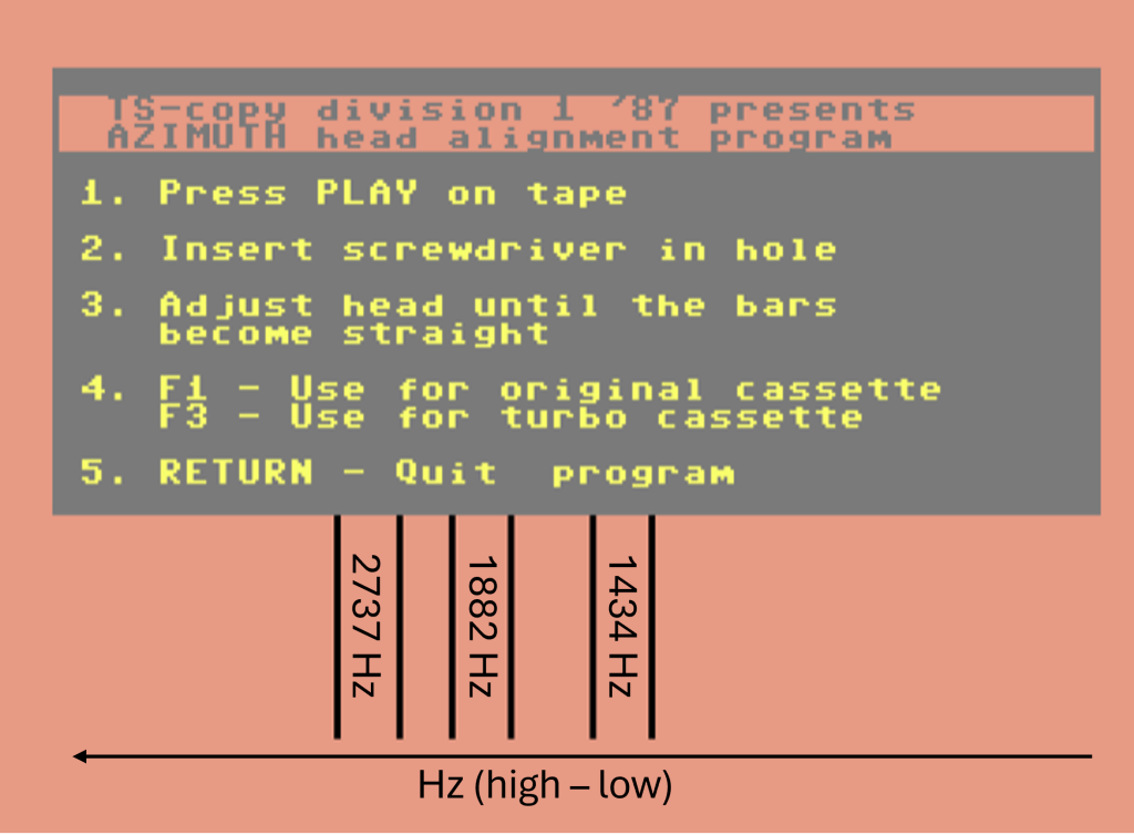
Commodore’s own tape format uses three different pulse types:
- Short 183 µs pulses (2737 Hz)
- Medium 266 µs pulses (1882 Hz)
- Long 349 µs pulses (1434 Hz)
The exact wave lengths vary between PAL and NTSC.
When the head azimuth is adjusted correctly , the entire r/w head sees the same pulse signal at any given time.
But when the head azimuth isn’t adjusted properly, the r/w head will be tilted at an angle relative to the signals on the tape, meaning that it will see a mix of two different pulse signals. This obviously raises the probability that it interprets something that was supposed to be a 0 (short pulse followed by medium) as a 1 (medium followed by short pulse) and vice versa.

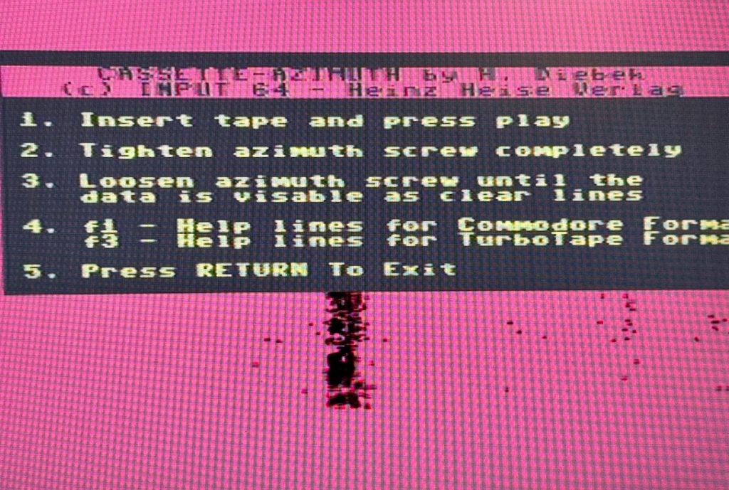
Head alignment software
The Azimuth head alignment program displays the pulse data directly on the screen. Rather than interpreting the pulses into bits and bytes, it simply gives you the wave lengths of the pulses passed on from the datasette.
Every time a pulse is read, the program draws a plot dependent on the wave length of the pulse. Hence, we have pulse wave length on the X-axis and time on the Y-axis.
When it works
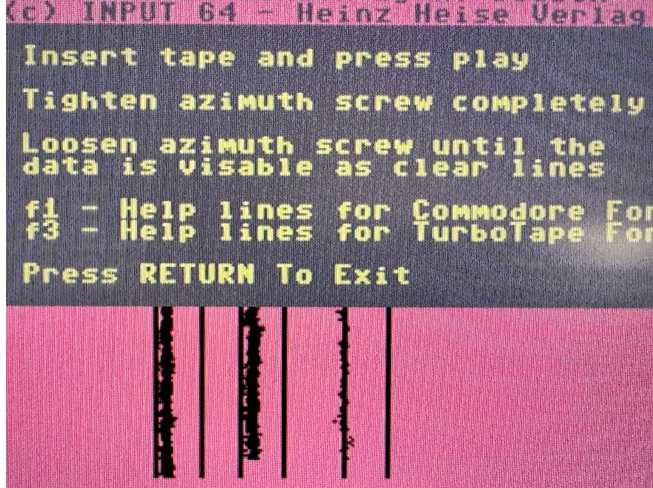
In the example below, you see a working tape during playback. The dots fall in a narrow pattern centered around the desired wave lengths, i.e. well within the help lines, Everything is just about as smooth as it will get in an analogue world.
When it doesn’t work
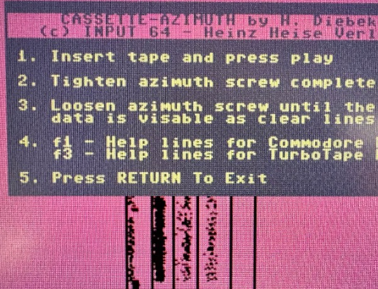
And then there is the other situation where nothing works. Below, you see the exact same part of the exact same tape as above but during playback on a datasette that doesn’t work. The datasette in question had an unknown issue, which wasn’t related to head azimuth, but it is still interesting to see the results.
What you should notice here is that many of the pulses seem to have the wrong wave length. Instead of either 2700 or 1800 Hz, the majority of the dots seem to land around 2300 Hz. Additionally, we have very few dots if any in the 1400 Hz band.
On other parts of the tape, the signal seemed to be shifted to the right, i.e. towards the longer wave lengths, which could suggest that there was a problem with the tape speed.
Strangely, I wasn’t able to confirm that theory when I tested the deck with a reference tape containing fixed frequency test sounds. I recorded the tape with three sections of test sounds, so that it matched the long, medium and short pulse wavelengths. Using 1530 Tapespeed Measurement, the datasette read all sounds at exactly the desired wavelengths, and when played in Azimuth, I god three razor sharp signal bars falling inside the help lines.
Indeed a puzzle.
A misaligned, dirty r/w head
Azimuth head alignment was designed to assist you in adjusting your r/w head. For that reason, I wanted to show what a misaligned, dirty r/w had looks like. The picture below is a good example. As clearly seen, we have dots being dispersed around the desired center (low sampling accuracy), which is what you would expect if the azimuth is adjusted incorrectly. We also see some dots showing up further to the right than they should. The latter observation is a clear indication that the r/w head needs cleaning.


Leave a Reply